Dual applicators
Independent top and bottom labelling heads with fine adjustment.
Automatic range
Top and underside label application for cartons, trays, sleeves and flat packs with stable product transfer.
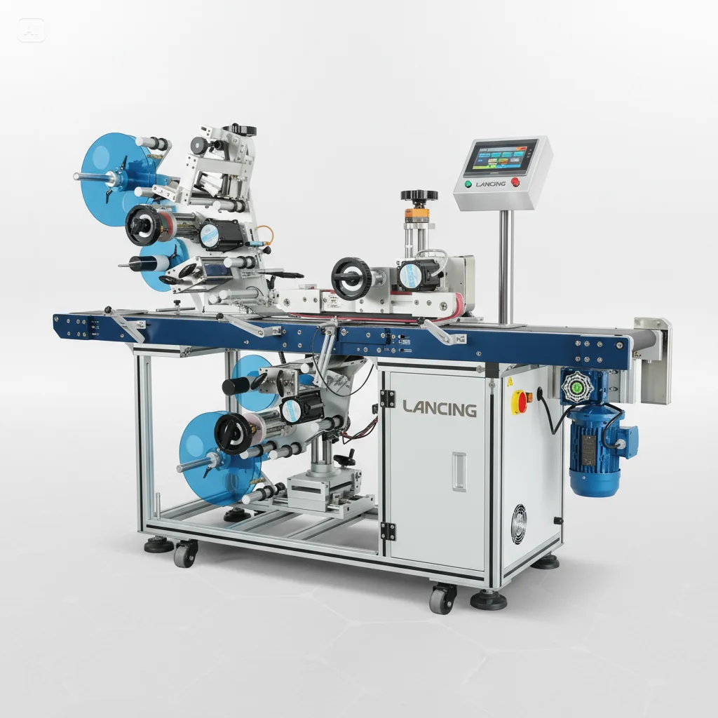
Machine features
Automatic top and bottom labelling machine for flat products, boxes, trays, sleeves, cartons and packs needing labels on both faces.
Independent top and bottom labelling heads with fine adjustment.
Stable product transfer across the lower labelling head.
Adjustable sensor sensitivity for different labels and packs.
Simple setup with recipe storage for repeat jobs.
Built for continuous-duty automatic production.
Can pair with date coding, conveyors and inspection systems.
Specification
Reference specifications are provided to help with early selection. Final machine specification depends on container dimensions, label material, label size, application position and required output.
| Model | LUB716Z reference |
|---|---|
| Accuracy | ±1 mm, product and label dependent |
| Application | Top and bottom labelling on flat products |
| Sensor | Adjustable sensitivity |
| Voltage | Typically 220 V |
| Speed | Model dependent |
| Products | Boxes, trays, sleeves and cartons |
| Conveyor | Split belt with guides |
| Coder options | Top and bottom date coding |
| Notes | Final specification varies by label and product size |
Applications
Tell us your container shape, dimensions, label material, label size, label position, target speed and whether the labeller needs to connect with a filler, capper, coder or inspection system.
Application-face engineering
Top and bottom labelling differs from twin-side bottle labelling because the underside applicator must reach the lower face without losing product control. Pack stiffness, thickness, leading edge and conveyor transfer are therefore central to the specification.
Confirm the minimum contact area available as the pack crosses the split conveyor. Flexible, very short or uneven products may need a different support arrangement.
Top and bottom labels can use different rolls and positions. Provide annotated drawings for both faces, including orientation and any print or barcode field.
Declare label material, liner and gap before sensor selection. If coding is required, define the coder, print position, data content and inspection method.
The existing specification table states a ±1 mm reference that is product and label dependent. Before this figure is used commercially, agree the horizontal and vertical datums, the normal conveyor speed, product spacing, sample size, allowable skew and how starts or stops will be treated. Run both applicators together using production label rolls.
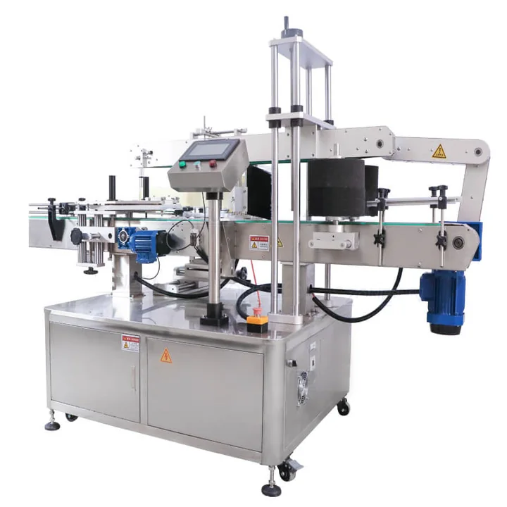
| Front/back twin-side route | Opposite vertical faces of bottles or shaped containers. Product orientation and side-belt stabilisation are central. |
|---|---|
| Top/bottom route | Upper and underside faces of cartons, trays, sleeves and flat products. Lower-head access and transfer stability are central. |
| Three-panel route | A separate specialist requirement where a third face or corner transition must be labelled. Supply drawings and samples before machinery is selected. |
| Wraparound route | A continuous label around a cylindrical pack. Compare the dedicated wraparound machinery range rather than specifying a top/bottom system. |
For the upper and lower applicators, provide finished label width and length, backing-paper width, core diameter, outside roll diameter, label gap, pitch, material and winding direction. State whether the label is opaque, metallic, film or transparent. If the two rolls differ, identify which belongs to each face.
Include normal product thickness, weight, leading-edge shape, surface condition and the available conveyor hand-off before and after the machine.
Specification questions
These points should be settled before reference accuracy, sensing and product transfer are accepted.
Use top and bottom labelling when the required application faces are the upper and underside surfaces of a stable carton, tray, sleeve or flat pack. Front and back labelling is for opposite vertical faces of a container.
The conveyor and product-transfer arrangement creates access for the lower applicator while keeping the pack supported as it crosses the dispense position.
No. The page states that the reference is product and label dependent. The final tolerance must be verified from agreed datums at the intended running condition.
They may be possible with an appropriate sensor, but the production label and liner should be tested because optical contrast and gap construction vary.
Coding can be considered where the print field, coder type, label speed and position are confirmed. The finished code should be checked at normal running conditions.
Supply representative products at normal thickness and weight, both label rolls, the intended label positions, target output and details of upstream and downstream transfer.
Lower-face access
The underside applicator needs access to the lower face while the conveyor still supports and controls the product. Product length, rigidity, weight distribution, base shape and the position of the lower label all influence the transfer arrangement.
A split-belt or bridged transfer can expose the base to the lower label head. The pack must remain stable while it crosses the opening, and the label must be presented without the leading or trailing edge catching the transfer. Short, flexible or uneven products need particular attention because they can dip, tilt or change speed.
Define the usable lower label area from the actual points that touch the conveyor. Feet, ribs, recessed bases and raised seams can interrupt wipe-down pressure or place the label where it immediately contacts a belt or guide.
The upper label can be wiped down by a roller, brush or belt selected for the product surface. The lower label may depend on the transfer geometry and product weight for controlled contact. Downstream belts, rollers and accumulation surfaces should be reviewed so they do not lift, scuff or displace a newly applied label.
Where variable data is printed, confirm which label head carries the coder, how print quality is checked and whether the printed area remains clear of wipe-down hardware.
| Product characteristic | Transfer or application risk | Evidence to obtain during a trial |
|---|---|---|
| Short or narrow pack | Insufficient support across the lower-head access gap. | Stable leading and trailing transfer at normal speed with the real product orientation. |
| Flexible tray or sleeve | Deflection can change label contact and product speed. | Video or observation of the lower face through the transfer, plus label-finish checks after exit. |
| Recessed or ribbed base | The label may bridge a recess or contact raised moulding features. | Confirmed usable label area and wipe-down on representative production samples. |
| Liquid or loose contents | Changing centre of gravity can make the pack rock or surge. | Tests in the filled state and at the normal line acceleration and stop conditions. |
| Cold, damp or oily surface | Adhesion and sensing can differ from clean room-temperature samples. | Production-condition samples with the intended label adhesive and storage history. |
| Coded lower label | Printing, inspection or fresh ink may conflict with wipe-down and transfer. | Legibility, barcode readability where relevant and protected transfer after application. |
Cartons, trays, sleeves and flat products are suited where upper and underside surfaces must be labelled in one pass.
Bottles and containers with opposing side panels normally require controlled orientation between two side applicators.
Top-plus-side, tamper-evident or three-panel applications need an annotated face map and may require a custom applicator arrangement.
Inspection and transfer
A lower label may be hidden as the product leaves the split-belt transfer. If underside inspection is required, the conveyor layout must create a clear view while keeping the pack supported and traceable to the reject device.
Confirm the pack spans the transfer gap and does not flex, tip or expose loose contents.
Provide clear sight of the finished lower label without guides, belts or another product obstructing the image.
Maintain identity from inspection trigger to reject, including starts, stops and closely spaced products.
Application questions
Top-and-bottom projects depend on clear access to both faces and controlled transfer over the lower application point.
Yes, independent application heads can usually be set to different target positions, subject to the selected machine and available adjustment range. Each face needs its own datum, trigger point and acceptance tolerance because the upper and lower labels may differ in size or purpose.
The sample trial should measure both faces separately and include normal product gaps.
Feet, skids, deep recesses, ribs, flaps, uneven bases and product features that hang below the support plane can obstruct label presentation or prevent smooth transfer over the lower head. A product may appear flat from above while offering only a small usable underside panel.
Provide underside photographs, drawings and physical samples before the conveyor path is finalised.
The lower head needs an open interval in which to present the label and reset before the next product reaches the application point. If packs touch or bridge the opening, the label path can be obstructed and the product may not be supported as intended.
Spacing equipment and upstream accumulation therefore form part of the top-and-bottom labelling specification.
A side-apply machine is usually the clearer route when the required labels belong on vertical pack faces, when the underside is not accessible, or when base features prevent stable transfer over a lower applicator. Top-and-bottom equipment is strongest for genuinely upper and lower surfaces.
Choose from the final label location and product presentation, not from the number of labels alone.